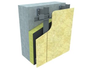
BSP KWRZ hanging system is used for invisible mechanical fixing of cladding panels on both exterior and interior walls. Due to its thick elements system was designed for heavier cladding such as concrete and stone panels. System consists of BSP KW1 brackets (alternatively BSP KW1 PAS brackets), BSP KWR1 and KWR2 profiles and horizontal BSP KWRZ profiles (which are also cut into pieces later used as hanging elements). All elements of BSP KWRZ system are made of extruded aluminium alloy EN AW 6060 T66 or EN AW 6063 T6.
BSP KW1 brackets are 4 mm thick. Their length (outreach) depends on cladding panels outreach and they are always chosen based on design and clients request. The size of a bracket depends on its type. Fixed brackets (load bearing ones) come in 150 and 120 mm versions, sliding ones (carrying only horizontal loads) come in 90 and 60 mm versions. There is additional aluminium piece on the side of the bracket that creates kind of a pocket that is used for fixing profiles and enables cladding leveling. All of the slots in the brackets were designed to ensure that aluminium expansion is possible. Brackets are fixed to buildings structure with anchors that are chosen based on static calculations. Pads/washers should be used together with the brackets to separate them from the wall or structure they are fixed to in order to avoid corrosion and decrease overall thermal conductivity. Recommended BSP pads are made of HDPE plastic material but alternatively PCV or EPDM ones can be used. BSP KW1 aluminium brackets are covered by the Technical Approval no. AT-15-9325/2014. They also have positive opinion of the Building Research Institute (ITB) regarding §225 of the Regulation of the Minister of Infrastructure regarding technical conditions that should be met by buildings and their location.
BSP KWR1 are T-profiles used at the joints of two horizontal profiles. BSP KWR2 are L-profiles used as a support in the middle of horizontal profile. Thickness of the profiles is 2 mm. They have 70 mm long side that guarantees high stiffness and enables large spacing of brackets. Grooved front side of profiles is 50 mm and 120 mm respectively for KWR2 and KWR1. 4,8×19 A2 self-drilling screws are used to connect profiles with brackets.
Horizontal BSP KWRZ hanging profiles are 4 mm thick. Thanks to that they are incredibly stiff and spacing of vertical supporting profile can be greater than compared to other systems of this kind available on market. Stiffness also prevents the profiles from twisting, which occurs due to heavy weight of panels.
BSP KWRZ hanging elements are just shorter pieces of 4 mm thick profile. They are turned by 180 degrees in relation to horizontal profiles and fixed to the back of the panel with under-cut anchors. There are two types of hanging elements: load bearing ones which are 120 mm wide (they carry vertical loads from the weight of the facade and horizontal suction and pressure wind loads) and sliding ones which are 60 mm wide (they carry only horizontal loads). Based on design and static calculations other width of elements may be used. Load bearing pieces are located in the upper part of cladding panel and use M6 adjustment screw. The screw enables installer to adjust and level vertical position of the panel by screwing or unscrewing it. Two nuts are used for adjustment: one is inserted into special rail and the second above it, alternatively threaded hole can be drilled and used. This system allows for 10 mm range of adjustment.
All elements of BSP substructure system have B durability class in accordance with PN-EN 1999-1-1:2011 and may be used without any additional anti-corrosion treatment in environments of class C1, C2 and C3 according to PN-EN ISO 12944-2:2001. If additional protective layer is applied – anodizing – they can be used in environment of class C4. All elements of the system are also classified as A1 class in the scope of reaction to fire according to PN-EN 13501-1+A1:2010 based on the decision of the European Commission No. 96/603/EC, 2000/605/EC and 2003/424/WE.
BSP KWRZ system should be installed in accordance with the workshop design prepared by engineers and designers with sufficient knowledge in the field of construction and building. The layout of the structure and the spacing between the elements (strength and resistance of the entire system) should be confirmed by the static calculations prepared by the engineer with qualifications in the filed of construction and building.
Realizations with this system